Arm Barrier Motor Docs
PRO-CARBON & DC ARM BARRIER OPERATION MANUAL
(Version P-103.)
Product installation and commissioning instructions
1. Product requirements for control board peripheral configuration
1.1. Power supply: 24V / 10A
1.2. Motor: 24V DC brushless motor
1.3 Vehicle detector or radar ground sensing
2. Product dimension drawing
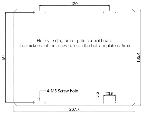
3. Control board wiring diagram
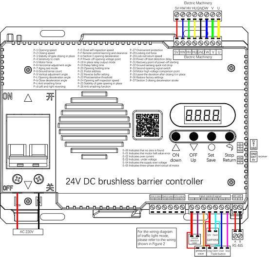
Note: it is best to use BVR wire, do not use network wire
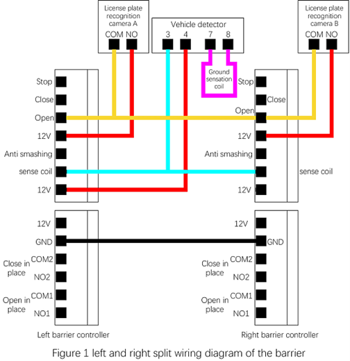
4. 4. Left and right split wiring diagram of barrier
5. Traffic light connetion diagram
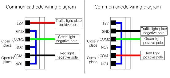
Figure 2: the wiring diagram of common cathode and common anode of traffic light
6. Barrier commissioning steps
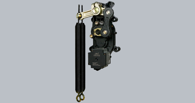
Step 1: Match the rod and spring::
Stop the gate lever at about 45 degrees and check whether the lever will slowly drop or open the gate (if the gate is opened, explain the spring tension is too large (the rod is allowed to open the brake slowly if the spring tension is slightly larger). If the rod falls indicating insufficient spring tension).
Adım 2: Limit of self inspection learning switch of track gate:
1. The normal startup of the controller is "00:00" and "e-00" alternately displayed. Press and hold the controller "close / turn up" for 2 seconds, and the track gate operates in the direction of closing. The controller scrolls from left to right to display "0 0 0 0", and the buzzer sounds rhythmically. When the motor runs to the closing limit, the controller displays static "0 0 0 0" and the buzzer stops ringing. At this time, the closing self-test is completed.
2. After the closing self-test is completed, press and hold the controller "open / down" for 2 seconds, and the track gate operates in the opening direction. The controller scrolls from left to right to display "0 0 0 0", and the buzzer sounds rhythmically. When the motor runs to the opening limit, the controller buzzer sounds for a long time. At this time, the opening self-test is completed, and the gate can operate normally.
Adım 3: Adjust the horizontal and vertical position of the gate lever:
1. The pole exceeds 90 degrees after driving to the position (adjust the P-9 parameter to a large scale); The pole is less than 90 degrees(reduce the P-9 parameter).
2. Close to the position where the pole is higher than the horizontal position (reduce the P-6 parameter); The pole is below the level position (increase P-6).
Note: 1. Judge whether the horizontal position of the fence pole and the advertising gate is in place (the pole contacts the ground motor will stop immediately (if the motor is still rotating after it is in place increase the P-6 parameter until the motor does not rotate after the pole reaches the ground.
2. After debugging the parameters, the switch needs to be operated to see the position change.
7. Key Operation
The controller has four keys, namely "on / down", "return / stop", "set / save" and "off / up". You can set various parameters of the main board through these four keys.
Shortcut key operation:
1. Press the "on / down" button once in the mode without inserting the motor cable to display the software version number; Press the "off / up" key once to display the software date.
2. In the normal working mode, under the display time page of the digital tube, short press "set / save" once to display the current value, short press "set / save" for the second time to display the change rate of hall, and short press "set / save" for the third time to display the internal voltage value of the controller; Short press "set / save" for the fourth time to display the power supply voltage value;
Key function description:
1. Set / save key: enter the setting state and save the setting value.
2. On / down key: press this key to open the gate in normal working state. After entering the setting state, you can use this key to add menu items or adjust the setting value upward. In the parameter setting state, short press to add one each time. Press and hold continuously until the maximum value is reached, and then add from the minimum value.
3. Off / up key: press this key to close the gate in normal working state. After entering the setting state, you can use this key to reduce menu items or adjust the setting value downward. In the parameter setting state, short press to subtract one at a time. Long press to continuously decrease to the minimum value and then decrease from the maximum value.
4. Return / stop key: in normal working state, press this key to stop the brake. In the setting state, you can exit the setting state or return to the previous menu.
8: Parameter menu
Operating instructions:
You can enter the parameter setting state by long pressing the "set / save" button for 3 seconds, and the LED will display "P-X". Select the menu items by pressing the two buttons "on / down" and "off / up" for a short time or a long time. Short press to increase or decrease one item at a time, and long press to increase or decrease continuously. Press the "set / save" key again to enter the setting of the specified item, and the "return / stop" key to exit the setting. After setting the specified parameters, you must press the "set / save" key to confirm it. The parameters set by pressing the "return / stop" key will not take effect. If there is no key within 45 seconds, the buzzer on the control panel will sound for a long time, exit the setting state and return to the normal working state.
|
Menu |
Function | Status | Default | Range |
| P-1 | Opening speed | The larger value indicates faster operation speed | 60 | 20-90 |
| P-2 | Closing speed | The larger value indicates faster operation speed | 50 | 20-90 |
| P-3 | Stability of gate closing in place | The smaller the value, the more stable it is. If it is too small, it may not be closed properly. | 15 | 4-50 |
| P-4 | Sensitivity to crash | The smaller value indicates more sensitive operation. If it is too small, product may lift automatically | 20 | 5-255 |
| P-5 | Motor force | This parameter is used with P-22 to reverse the starting force | 30 | 10-250 |
| P-6 | Horizontal adjustment angle | The smaller the value, the smaller the brake rod angle | 20 | 2-255 |
| P-7 | Aging test mode | 0: manual, 1-5: normal aging, 6: half stroke operation | 0 | 0-6 |
| P-8 | Ground sense count | 0: without counting, 1: with counting, 4: Fleet mode | 0 | 0-1,4 |
| P-9 | Vertical adjustment angle | The smaller the value, the smaller the opening angle | 20 | 2-255 |
| P-L | Opening deceleration angle | This numerical angle begins to slow down on a horizontal basi | 65 | 20-85 |
| P-b | Close deceleration angle | This numerical angle begins to slow down on a horizontal basis | 30 | 10-80 |
| P-c | Anti smashing force | The larger the value, the greater the anti-smash car strength. If the value is greater than 100, the anti-smashing function is cancelled | 65 | 5-101 |
| P-d | Left and right reversing | If the movement is the same as the control board button This parameter does not change. Otherwise, you will change this parameter | 1 | 1-2 |
| P-E | Close self inspection speed | The larger the value, the faster the speed. Only for power-on self-check and shutdown | 20 | 2-90 |
| P-F | Remote control learning and clearance |
000 indicates waiting for remote control learning 253 means to clear the learned remote controller |
0 | 000-253 |
| P-H |
Section 2 opening deceleration |
The parameter is set within the first deceleration | 0 | 0-30 |
| P-P | Power-off opening voltage point | When the power is off, the voltage is detected below this value, start the lift lever(batteries or super capacitor plates need to be added). Unit: 0.1V | 225 | 100-250 |
| P-18 | In place relay output mode |
0: traffic light mode 1: in place mode 3: Light sensing mode 5: in place relay output for 2 seconds |
0 | 0-5 |
| P-19 | Delay falling time | The unit is seconds. | 0 | 0-255 |
| P-20 | Opening holding time | The unit is seconds.0 Is not automatically closed (This parameter is generally not recommended.) | 0 | 0-255 |
| P-21 | Postal address | 485 communication address | 1 | 1-255 |
| P-22 | Reverse buffer setting | Reverse the buffer stroke, the larger the value, the smaller the buffer stroke, the smaller the buffer stroke | 50 | 1-90 |
| P-23 | Photosensitive threshold | - | 75 | 10-100 |
| P-24 | Opening self inspection speed | The larger the value, the faster the speed. Only used for power-on self-check and gate opening | 20 | 2-90 |
| P-25 | Stability of gate opening in place | The smaller the value, the more stable, too small may not be in place. | 15 | 4-50 |
| P-26 | Anti smashing function | 0: Close, 1: Open | 1 | 0-1 |
| P-27 | Overcurrent protection | The unit is 0.1A | 80 | 20-100 |
| P-28 | Locking rod force (not recommended to adjust) | The greater the value, the greater the force during the lock bar. Recommend fine-tuning starting from the appropriate value. This value is too small and may not be locked. This value is too large, bad for the movement and the motherboard. | 80 | 45-160 |
| P-29 | Lock rod return speed | The larger the value, the faster the speed is. The recommended speed should not be too fast | 70 | 10-255 |
| P-30 | Power off start detection delay | Detect the delay value, 0 indicates that the power-off starting function is invalid | 0 | 0-200 |
| P-31 | Recovery point of power-off starting | After power off and switching on, the battery or super capacitor board still has power. At this time, the comparison point of mains power calls. Unit: 0.1V | 235 | 200-250 |
| P-32 | Ground sensing quick rod drop | After opening, after the ground sense fails, without waiting for the gate to open in place, But immediately off the gate; 0: close, 1: open | 0 | 0-1 |
| P-33 |
Second opening signal switch |
When P26=0, the corresponding port is available as The second opening signal switch; 0: off, 1: on | 0 | 0-1 |
| P-34 | Motor high voltage comparison point | The unit is 0.1V. When there is no spring, When the bar weight is heavy, the drop brake may produce high pressure; When the spring pull is too high, lifting the brake may also produce high pressure. This value can be adjusted appropriately to run better | 310 | 250-450 |
| P-35 | Leave the deviation after closing it in place |
After it is closed in place, it leaves a larger position. This value reflects the degree of deviation. The larger the value, the larger the deviation |
10 | 10-250 |
| P-36 | Restore factory settings |
1: Only clear the parameter table, 2: clear the parameter table and the remote controller, 3: Data backup, 4: restore backup, 5: Only clear the remote controller, 6: self check again 2: clear the parameter table and the remote controller, 3: Data backup, 4: restore backup, 5: Only clear the remote controller, 6: self check again |
0 | 0-6 |
| P-37 | Section 2 closing deceleration stroke | The parameter is set within the first deceleration | 0 | 0-30 |
Digital Tube status: display "E-00" indicates that no zero is found
; display "E-01" indicates the motor Hall value error; display "E-02" indicates over current;
display "E-03" indicates under voltage; "E-04" indicates the supply over voltage; "E-05"
indicates the three-phase short circuit of the motor;
For all places involving angles, the closing position is 0 degrees
When the power supply voltage is too large (> 27V) or too small (< 18V), the controller will automatically protect and give an alarm,
When the controller is protected, the motor, light box, ground sensor and other equipment will not work
9. Remote Control Function
9.1. Remote control pairing: long press the controller "set / save" for three seconds, find the P-F item, and press the "set / save" again to display "000". At this time, press any key of the remote control. At this time, after the controller makes a long sound, the display changes to P-F, indicating that the remote control is matched successfully.
9.2. Clear the remote controller: long press "set / save" on the main board for three seconds, find the P-F item, press "set / save" again to display "000", adjust the value to 253, and press "set / save" again. At this time, after the main board makes a long sound, the display changes to P-F, and all remote controllers will be cleared.
9.3. Filo modu: Long press "set / save" on the controller for three seconds, find item p-8, and then press "set / save" to display "0", adjust the value to 4, and then press "set / save" to exit the menu; After the road gate is opened in place, press the stop button of the remote controller for more than 2 seconds, and the fleet mode will start; To turn off the fleet mode, just press the off key of the remote controller.
10. Common Problems and Solutions
1. The self-inspection is not successful, and the gate is not running normally Solution: check whether the left-right rotation mode of the P-D motor matches the current motor or not (you can re power on the controller after changing the parameters and conduct self-test again. Please refer to "Chapter 1, subsection 6, step 2" for whether the self-test of the track gate is normal)
2. The vertical or horizontal position of the gate rod is not in place
Solution: adjust the controller menu P-9 or P-6 parameters (refer to the parameter table for menu functions)
3. How to correctly judge whether the gate is really in place
Solution:
a. Set the P-18 parameter of the controller to 1. If the relay is opened or closed once, it indicates that it has been opened / closed in place
b. Pay attention to observe whether the motor stops when the gate lever is in place, which means it is in place. If the gate lever is in place and the motor is still running, it is necessary to change the P-6 or P-9 parameters.
c. In the process of switching on and off, the nixie tube will have a dynamic "1" display. If the nixie tube display returns to the time interface, it indicates that it has been in place
4. Failure of rebound function in case of resistance
Solution: A. check whether the P-C parameter turns on the resistance rebound (if the controller parameter is greater than 100, the resistance rebound function fails)
5. The gate suddenly runs in the opposite direction during normal Operation.
Solution: increase the value of P-C rebound function parameter
6. The gate was opened again when the gate was almost in place
Solution: increase the stability value of P-3 in place
7. Error codes and Solutions
| Warning Code | Instruction | Solutions |
| E-00 | No self-test failed or the self-test failed | Re-self-test; check whether the motor wire is correct |
| E-01 | System failure |
Check whether the motor line sequence is correct; Check whether the motor Hall is damaged; Check whether the motor line contact is reliable |
| E-02 | Over current | Whether the P27 setting is too small; the spring strength is too strong. |
| E-03 | Under voltage | Check whether the output voltage of the power supply is normal |
| E-04 | Over voltage |
Check whether the output voltage of the power supply is normal |
| E-05 | Three-phase short circuit of motor(any input / output is invalid) |
Check whether the output voltage of the power supply is normal |